The Duffing Oscillator
This lab is due Thursday, April 25, 2002, in class.
You may find it easiest to use the software called IDE (Interactive
DIfferential Equations) in the old Macintosh lab in MCS. In IDE, you
should open the tool called Duffing Oscillator. You may, of
course, use other differential equation solvers, but you will not see
all of the images that you see in IDE.
You will be graded on exactly what is asked for in the instructions
below. You need not turn in any additional data, graphs, paragraphs,
etc. You should submit only what is called for, and in the order the
questions are asked. It is perfectly
acceptable to hand in hand-drawn figures,
since you cannot print pictures using IDE.
Remember that you will be graded on your use
of English, including spelling, punctuation, logic, as well as the
mathematics.
IMPORTANT: The work you submit should be your own and nobody else's.
Any exceptions to this will be dealt with harshly. Copying or
paraphrasing another student's lab report is strictly forbidden.
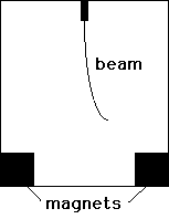
Lab. In this lab you will investigate a nonlinear system of
differential equations that governs the motion of the Duffing
oscillator. This contraption consists of flexible steel beam attached
to the top center of a box. There are magnets on either side of the
bottom of the box toward which the beam is attracted. The
differential equation describes the motion of the tip of this beam as
the box is moved periodically from side to side. Here is the picture
of the system.

| | |
The differential equation for the Duffing oscillator is
x" = -x(x2 - k) -bx' + A cos(wt)
or, as a system
dx/dt = v
dv/dt = -x(x2 - k) -bv + A cos(wt).
Here A is the magnitude of the forcing function, w is
the forcing frequency, b is the damping coefficient, and
k is related to the stiffness of the beam. The center of the
box is located at x = 0, with x > 0 to the right.
|
For the entire lab, we will keep k = 1 and w = 0.6.
Before going to the lab, you should work out #1 below. In the lab
you should use the IDE tool called the Duffing Oscillator to
investigate this system of equations.
In this tool you will see three images: the phase plane, the
x(t) graphs, and the motion of the beam. You should turn off
the velocity and acceleration graphs, so that you see only the (green)
graph of x(t).
You should also be aware that the behavior of solutions of
this system of differential equations
is still not completely understood and is,
in fact, the subject of considerable mathematical research. I do not
expect that you will be able to completely understand this system.
Your goal, especially in #6-8 below, is to view some of the complexity
of this simple mechanical system.
1. You will first investigate the autonomous case, i.e., when
A = 0. Find all equilibrium points for the system when A =
0. What configurations of the beam do these equilibrium points
correspond to? Using linearization, determine the types of these
equilibrium points. For which values of the damping constant b
do you expect bifurcations to occur?
2. Use IDE as an aid
to sketch the phase plane for this system when A =
b = 0. Be sure to include the nullclines in your sketch.
Using this sketch,
explain in a brief paragraph
what happens to the beam if
the beam is released from position x with velocity equal to 0
for all values of x. Discuss what changes occur as you vary x.
3. Now sketch the phase plane when b > 0, say, for
definiteness, when b = 0.05. What happens to the nullclines
when b becomes positive? What bifurcations occur when b
becomes positive?
4. In a paragraph or two, describe what now happens to the beam
when it is released from position x = 0 with positive velocity
v > 0 for all values of v, i.e., solution curves that
begin on the positive v-axis. You should see different
behaviors depending upon v. What do you expect will happen for
values of v that are larger than those shown on the screen?
5. Provide a sketch of the solution curves in the phase plane
that separate different types of behaviors.
6. Now turn on the forcing. Suppose A = 0.3, b = 0.2 and w
= 0.6. What can you say about the ultimate behavior of the
beam for various initial conditions along the x-axis? Provide
sketches of the different behaviors in the phase plane and
describe all possible eventual motions of the beam that you find. Be
sure to let solutions run for a long time. You
may use the "clear transients" button to see the eventual motion of the
solution curve in the phase plane.
7. Now change b to 0.15. Do you see a bifurcation?
What has changed? Why is this bifurcation called a "period doubling
bifurcation?"
8. Finally let b = 0. What can you say about the
ultimate behavior of solutions now?